
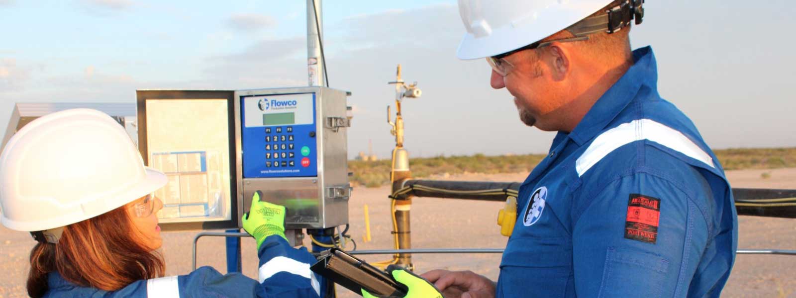
Our experienced team can diagnose your unique production challenge
Every well is unique, and our qualified experts can help with your short-term challenges and long-term goals. You can trust Flowco for field-proven, reliable artificial lift solutions. We are artificial lift. It’s what we do. All day. Every day.
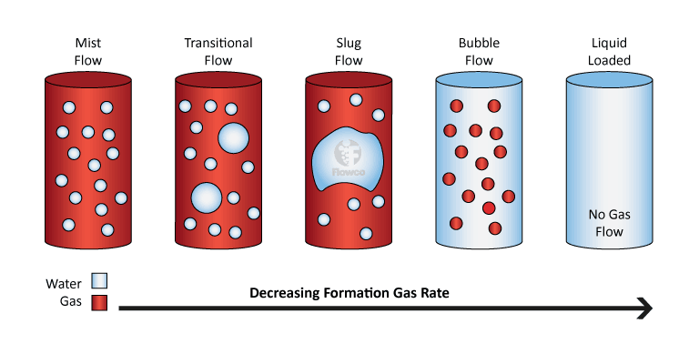
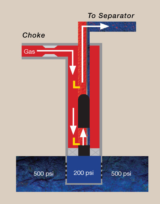
Liquid loading is the accumulation of liquids (water or condensate or both) in the wellbore, and can be addressed by several methods of artificial lift, including plunger lift, gas lift, and capillary injection systems. When the weight of a liquid droplet due to gravity overcomes the drag exerted by the rising gas in a column, liquid falls back and tends to accumulate at the bottom of the well. It occurs in vertical or deviated wells during production from natural gas reservoirs as a consequence of condensation and coalescence of liquids from gas streams.
This is common in both offshore and onshore production systems. Engineers are often tasked to identify and correct this type of production problem through operational changes (e.g. reducing wellhead pressure). Similarly, based on field experience, engineers can plan the well completion in advance and/or select tubing size to address expected liquid loading issues.
Liquid loading has remained a menace and a fundamental problem in gas wells as all gas wells will undergo this phase in their productive life cycle. It is more pronounced in aging fields but can also occur in new wells having poor completion designs. When improperly managed, liquid loading will cause a drastic drop in production and when left unattended, will cause the well to cease production.
Several methods are available in aiding and managing production when severe liquid loading occurs.
Still experiencing issues or have questions? We can help. Our experts can work with your production team or create a custom well design. Contact us to coordinate with our local team and we will get back with you promptly.
There will be days when the hydrocarbons produced from your well is not what you were expecting, or you experience inconsistent production. Most production tends to be steady over time. A big decrease from what’s expected will more likely be an indicator of a problem. Often, the size of the change, can be a good indicator of where the problem lies.
When the problem is downhole, analysis can get quite complex. A few problems that can cause a loss of production can be addressed from the surface, others may require shutdown and workover to remedy. Also, changes occur to the well over the production lifecycle. A decreased production rate may be an indicator that a new form of lift is required, such as replacement of an electric submersible pump (ESP) system with a gas lift system, or introduction of a gas-assisted plunger lift system to increase production rates to their former levels.
Continuous monitoring with the help of a downhole gauge and Supervisory Control and Data Acquisition SCADA system can help you anticipate a failing pump so that small problems do not develop into bigger, more expensive ones.
The tubing string may fail to build pressure. This might indicate a hole in the tubing or a collar leak. A tubing integrity test is necessary to determine if there is communication in the tubing string. Flowco can provide a procedure for testing this, or provide the man-power to assist in the process of testing. If gas lift valves are included in the well already, Flowco can aid in ‘Rocking the Gas Lift Valves’.
Still experiencing issues or have questions? We can help. Our gas lift experts can work with your production team or create a custom well design. Contact us to coordinate with our local team and we will get back with you promptly.
Choosing a proper injection pressure is critical to a gas lift system design. Several factors may affect the choice of an injection-gas pressure. However, one primary factor stands out above all others. To obtain the maximum benefit from the injected gas, it must be injected as near the producing interval as possible.
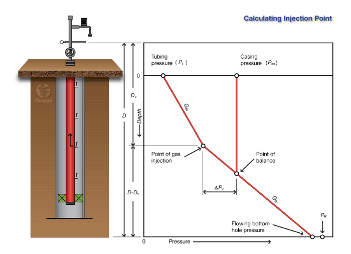
The injection-gas pressure at depth must be greater than the flowing producing pressure at the same depth. Any compromise with this principle will result in less pressure drawdown and a less efficient operation. High volumes of gas injected in the upper part of the fluid column will not have the same effect as a much smaller volume of gas injected near the producing formation depth because the fluid density is reduced only above the point of gas injection.
Selection of higher injection pressure facilitates fewer gas lift valves as it results in a greater pressure differential between the injection pressure and the flowing tubing pressure; thereby, allowing a greater spacing between valves.
Injection gas volume is also a critical component to how the well performs. Too little injection gas may not unload the well to the deepest point of injection and will cause the well to underperform. Excessive injection gas will induce pressure losses due to friction which will cause the well to underperform as well. Once the injection depth is reached and the well stabilizes, the injection gas volume can usually be decreased to conserve horsepower.
Still experiencing issues or have questions? We can help. Our gas lift experts can work with your production team or create a custom well design. Contact us to coordinate with our local team and we will get back with you promptly.
An artificial lift system should be chosen and designed during the initial planning phase of an oil field. However, in the haste to get a field on production, artificial lift may not be considered until after other production facilities are designed and installed. It is difficult to choose and install the optimum artificial lift system after the surface production decisions have been made. This is especially true in the case of gas lift.
Continuous-flow installation designs vary depending on whether complete and precise well data are known. Reliable inflow well performance and an accurate multiphase-flow correlation are required to establish the approximate point of gas injection in deep wells. When the well data is limited or questionable, the exact point of gas injection cannot be calculated accurately in many wells. This being the case in today’s depletion drive and unconventional reservoirs, your Flowco specialist will design the gas lift solution to perform over the life of the system. When designing your casing, skimping on casing size can ultimately cost lost production that is many times greater than any savings from smaller pipe and hole size. The same is true in flowline size and length. In most cases, increasing the size of the flowline does not compensate for the backpressure generated by the added pipe length. Any item of production equipment that increases backpressure at the wellhead, whether it be wellhead chokes, small flowlines, excessive number of bends, undersized gathering manifolds and separators, or high compressor suction pressure, seriously impacts the operation of a gas lift system.